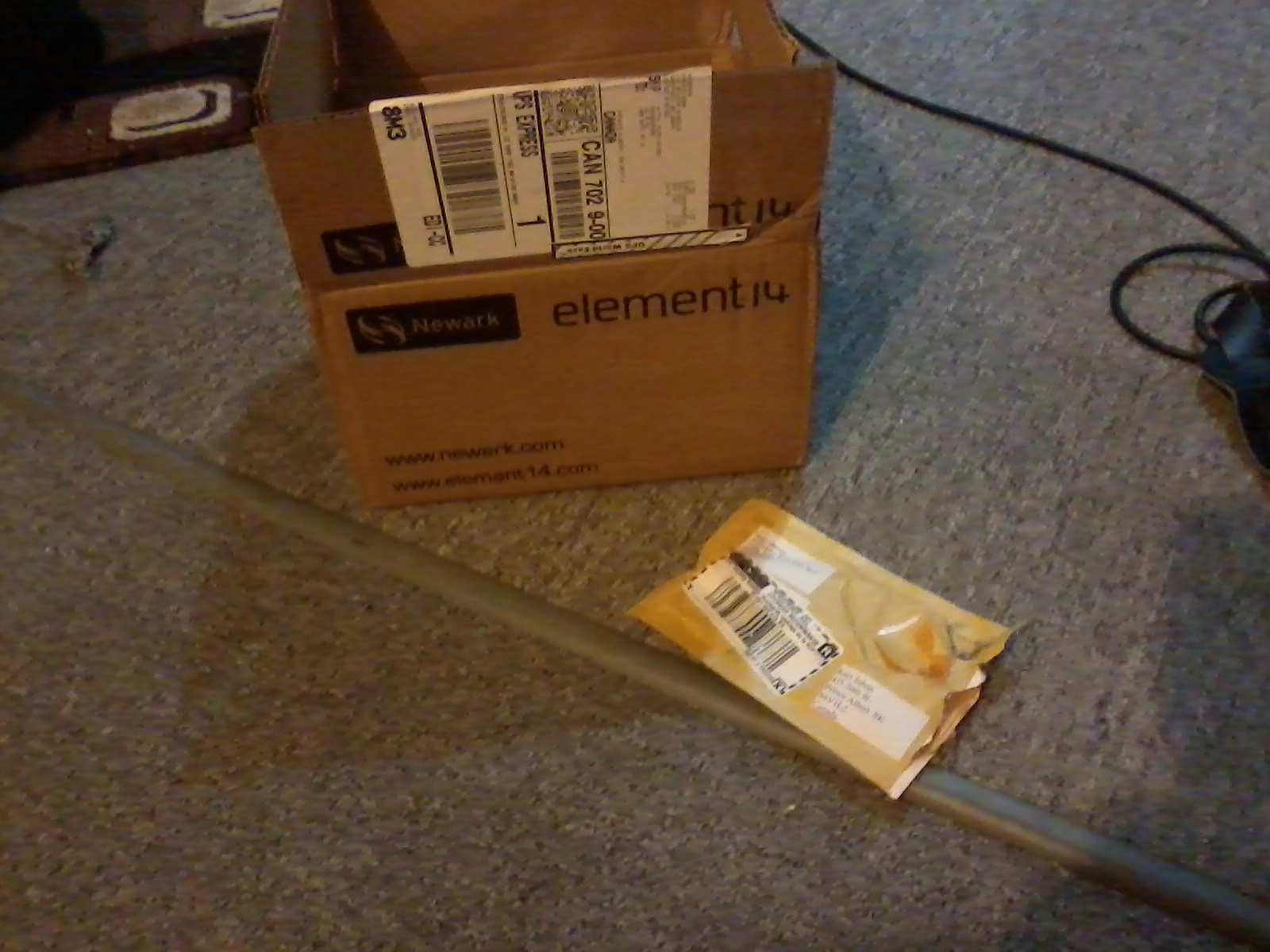
 So My packaged finally arrived, I had recieved a new vic by mail just shortly before. I wasn't sure if I was ready, but like most things I do I just jumped in and worried about it later.
So My packaged finally arrived, I had recieved a new vic by mail just shortly before. I wasn't sure if I was ready, but like most things I do I just jumped in and worried about it later.
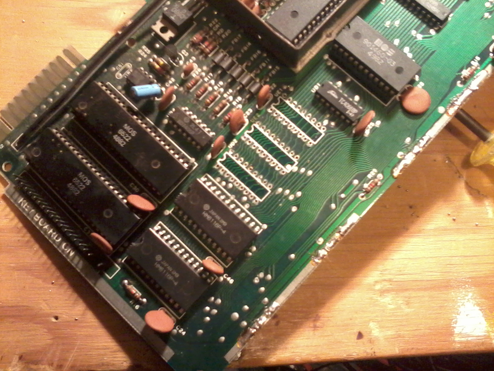 This was where the hard work really started. Chips are very difficult to remove. I bought a little vise thing to hold the board while I applied heat with the soldering iron from the top and used a desoldering bumb on the bottom. This still didn't always work. I tried using a desoldering braid but I found it didn't soak up the solder like I wanted. At any rate I slowly removed the chips the 1/2 K chips were first. On a side note if you never want to return your vic to it's original state, you COULD break these out, but you would have to becareful not to do any damamge to the circuit board.
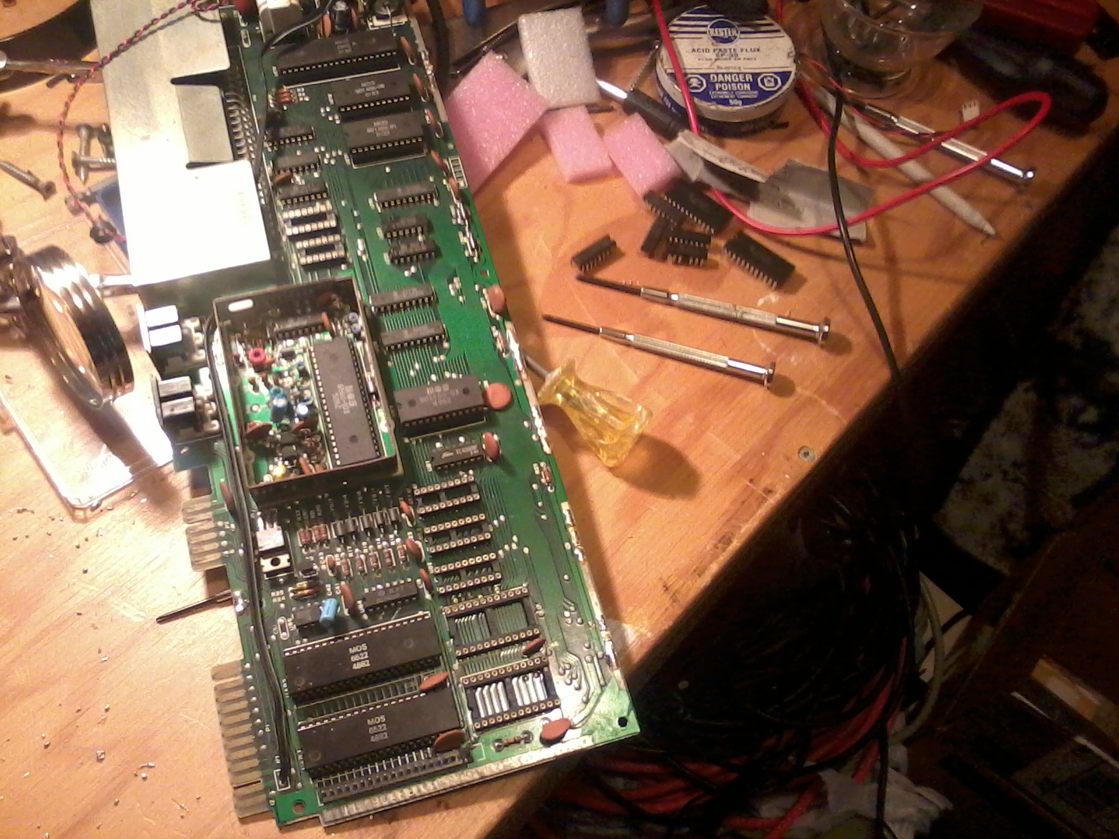
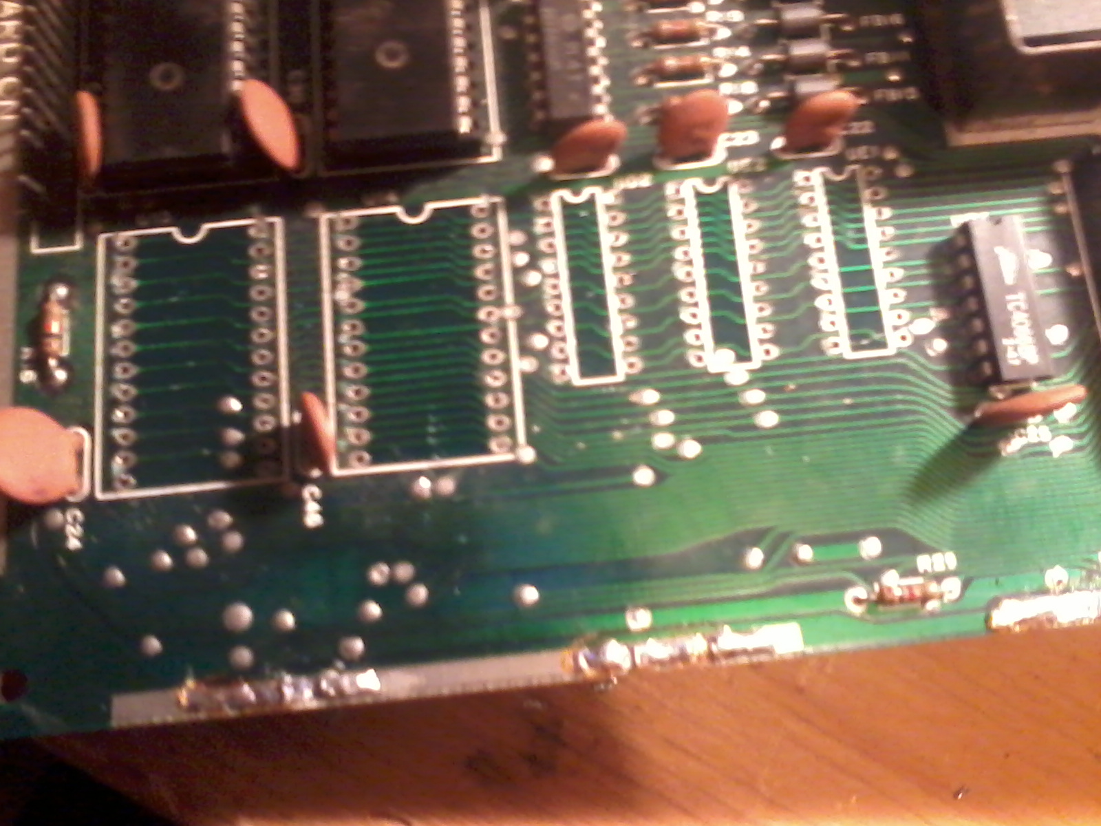 For some reason I pulled out the 2K chips next. By now I found my best secret weapon was patients. I think this was night 2.
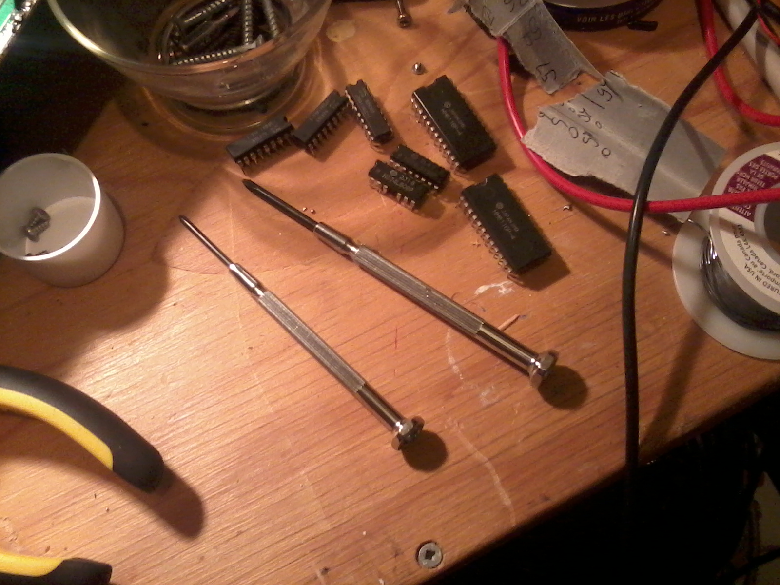 Here are the removed chips, just off center is my broken 74ls08. I ordered another one and waited till it arrived before doing anything else.
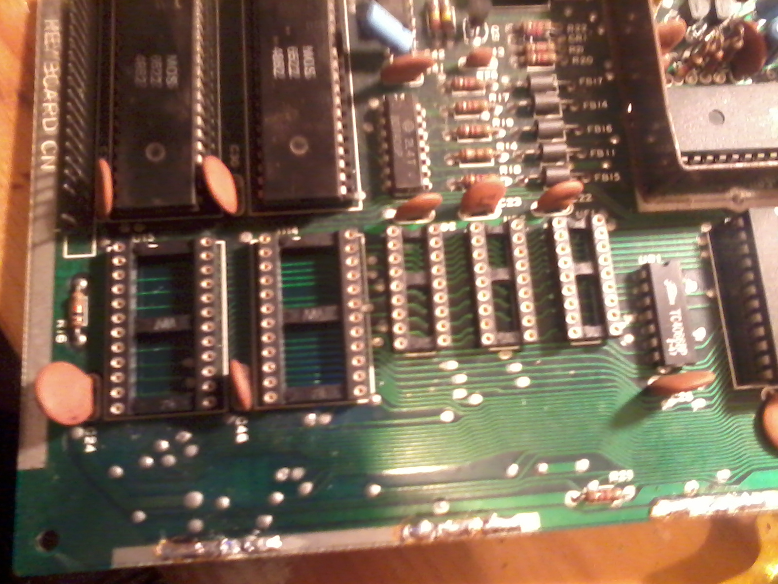 I tried to clean up the chip holes and then inserted and soldered the DIP sockets. It only took about 10 minutes. It was at this point I realized the most difficult part was done. I'm just glad I didn't have to desolder the VIAs or the 6502 itself. On this particular board those had DIP sockets anyway.
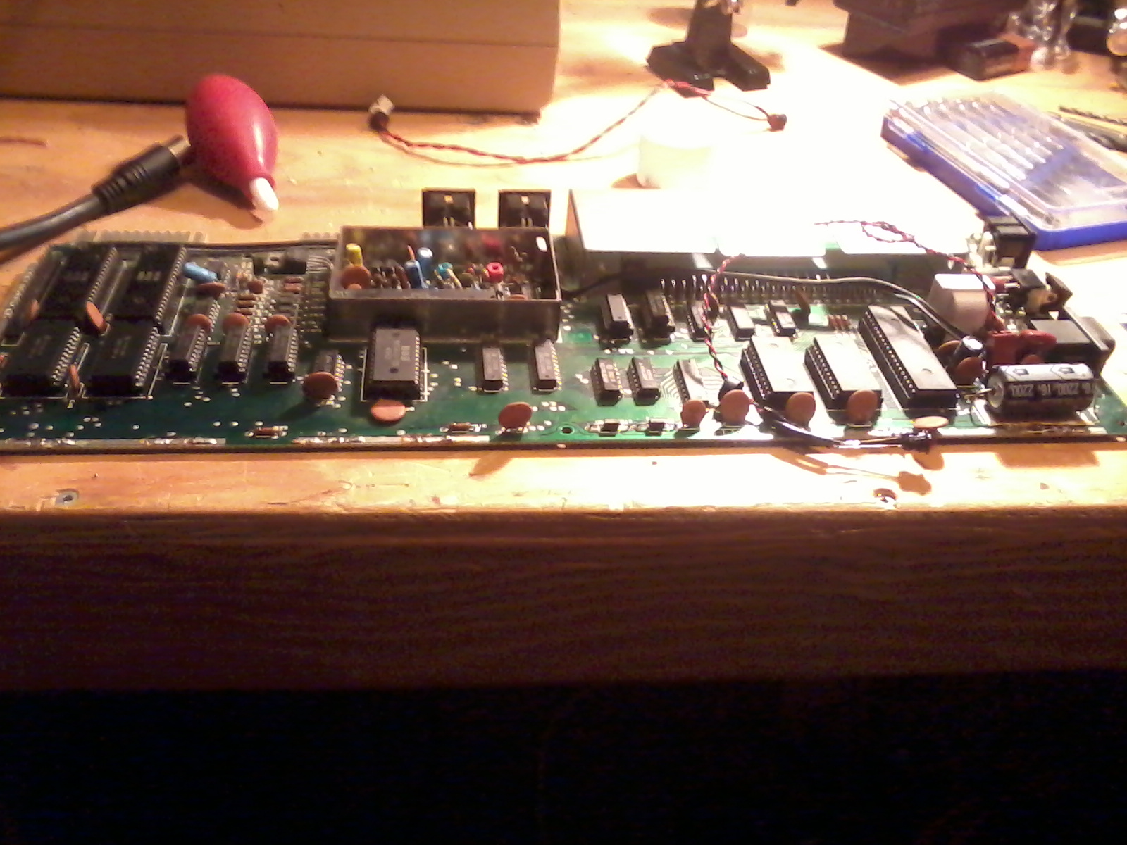 I straightened the old chips legs as best as I could and seated them in the sockets. This took a while. I would suggest care here as the legs get soft and I was very afraid of breaking them.
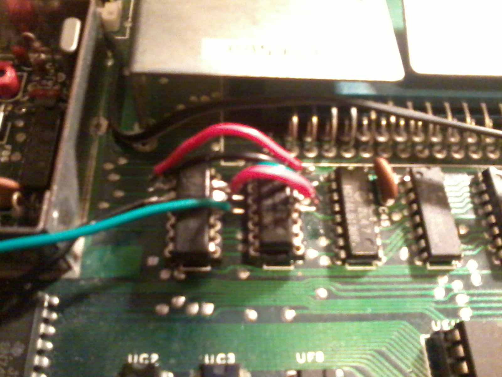 The next night I started the re-wiring. My wiring looks more like frankenstiens monster than Mikes craftmanship, but luckily it only matters if it works, not if it looks nice.
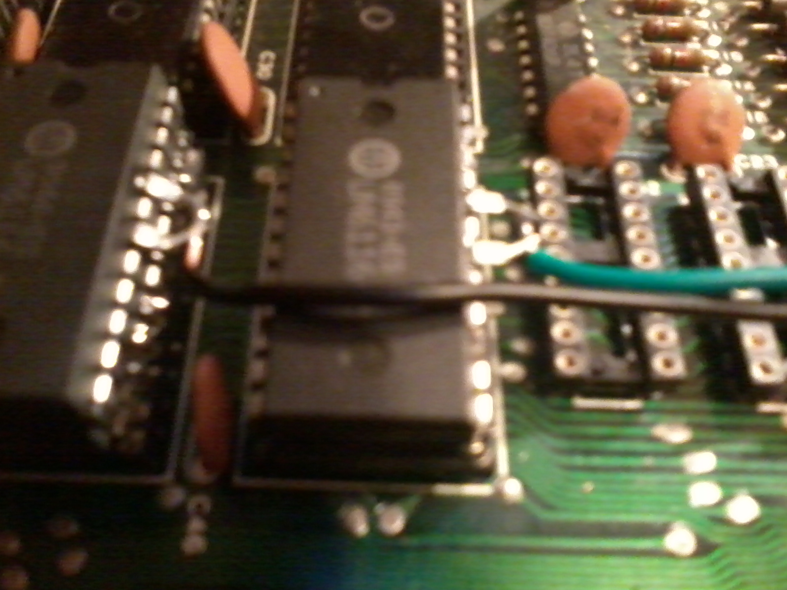 This was a bit tricky, bu again slow and steady. I left a bit longer end on the wire to touch both legs. I also soldered both chips together BEFORE placing them in the DIP socket. I was a bit worried about soldering the chips to the socket. That would have been a nightmare to try and undo.
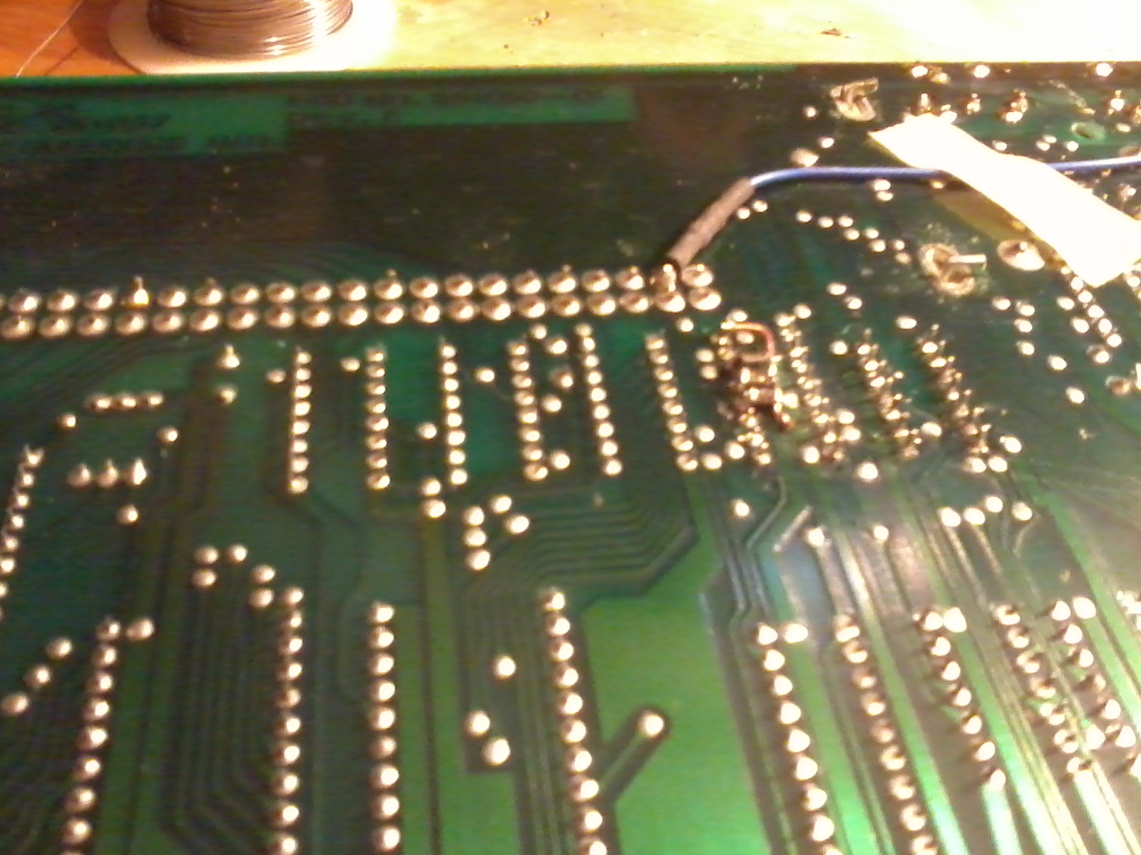 The SMD resistors are too small to actually hold, so you have to push them around with the soldering iron and try to get them in the right position. This took a while. I think I called it a night after this.
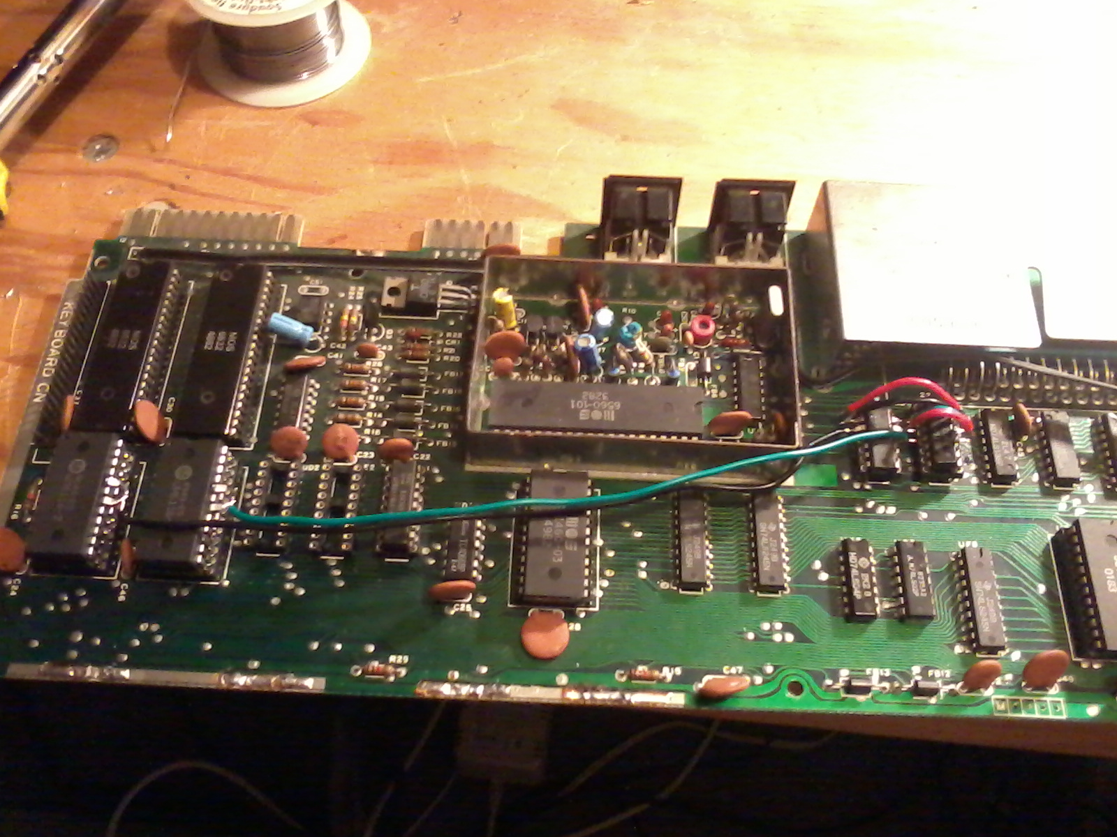
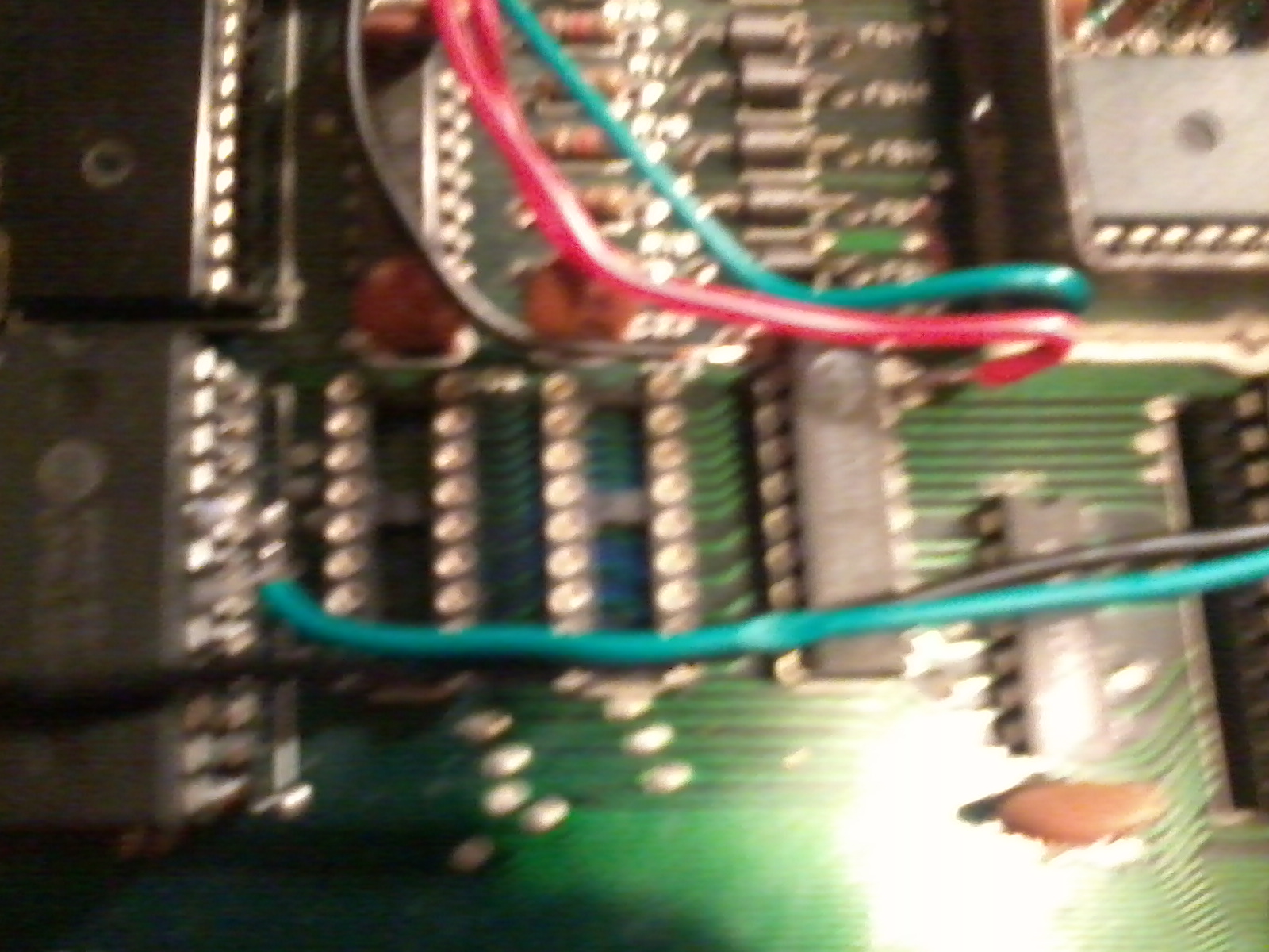 The last part of the wiring wasn't too bad, the SMD capacitor, was a bit easier to do. Plus it is the only one. The wire to supply power to the new RAM chip; I just placed it in the hole and soldered it in, and the blob covered the end of the little capacitor. The other four wires go to the user port. I scratched the copper a bit to help the solder stick when attaching the wires to the user port.
 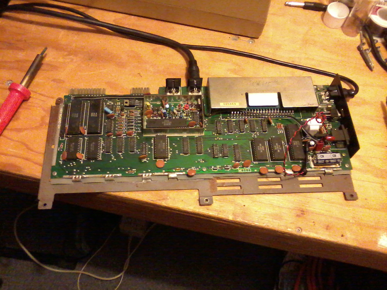 Just checking the the board works as it should.
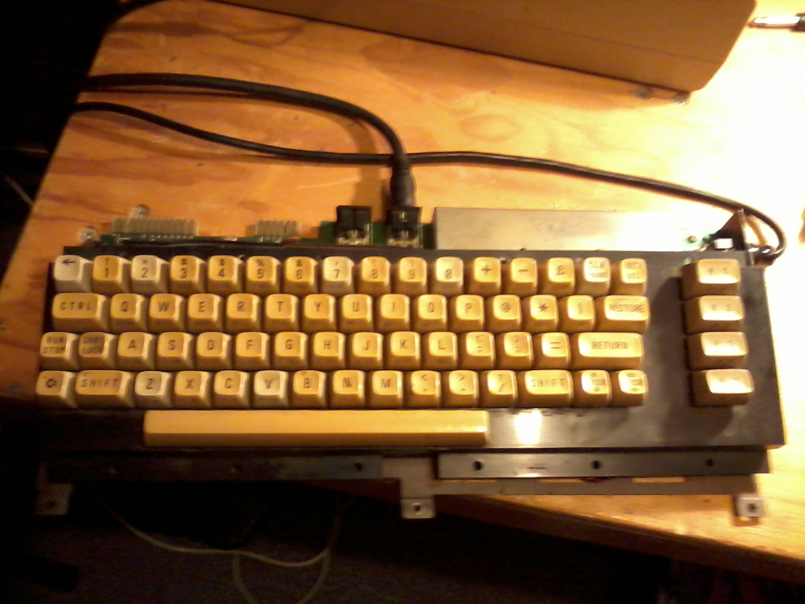 Hooked up a 64c keyboard, because I can.
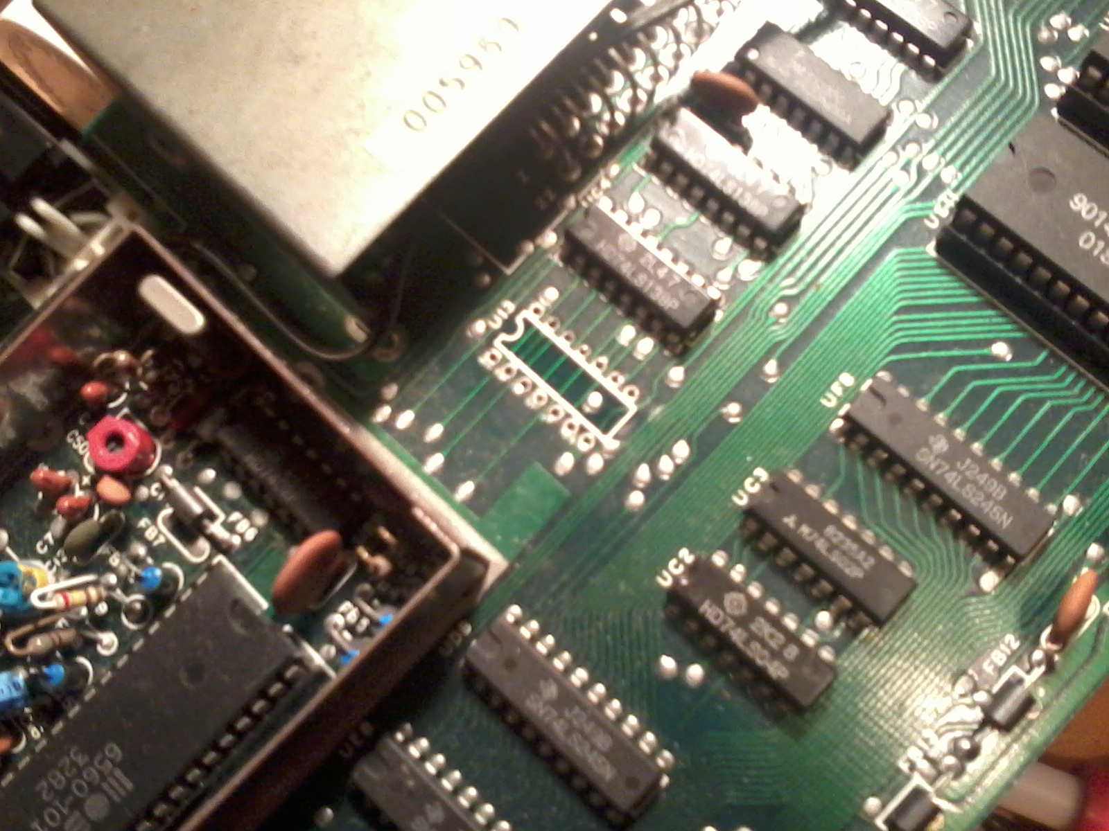 Next was the 74ls08 which I broke. I was very sad, but I was able to order another as a spare.
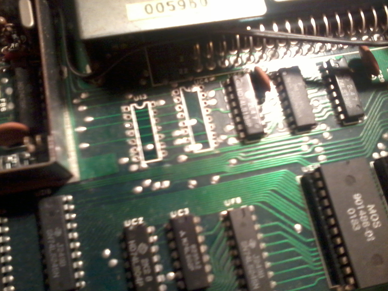 And finally the last chip.
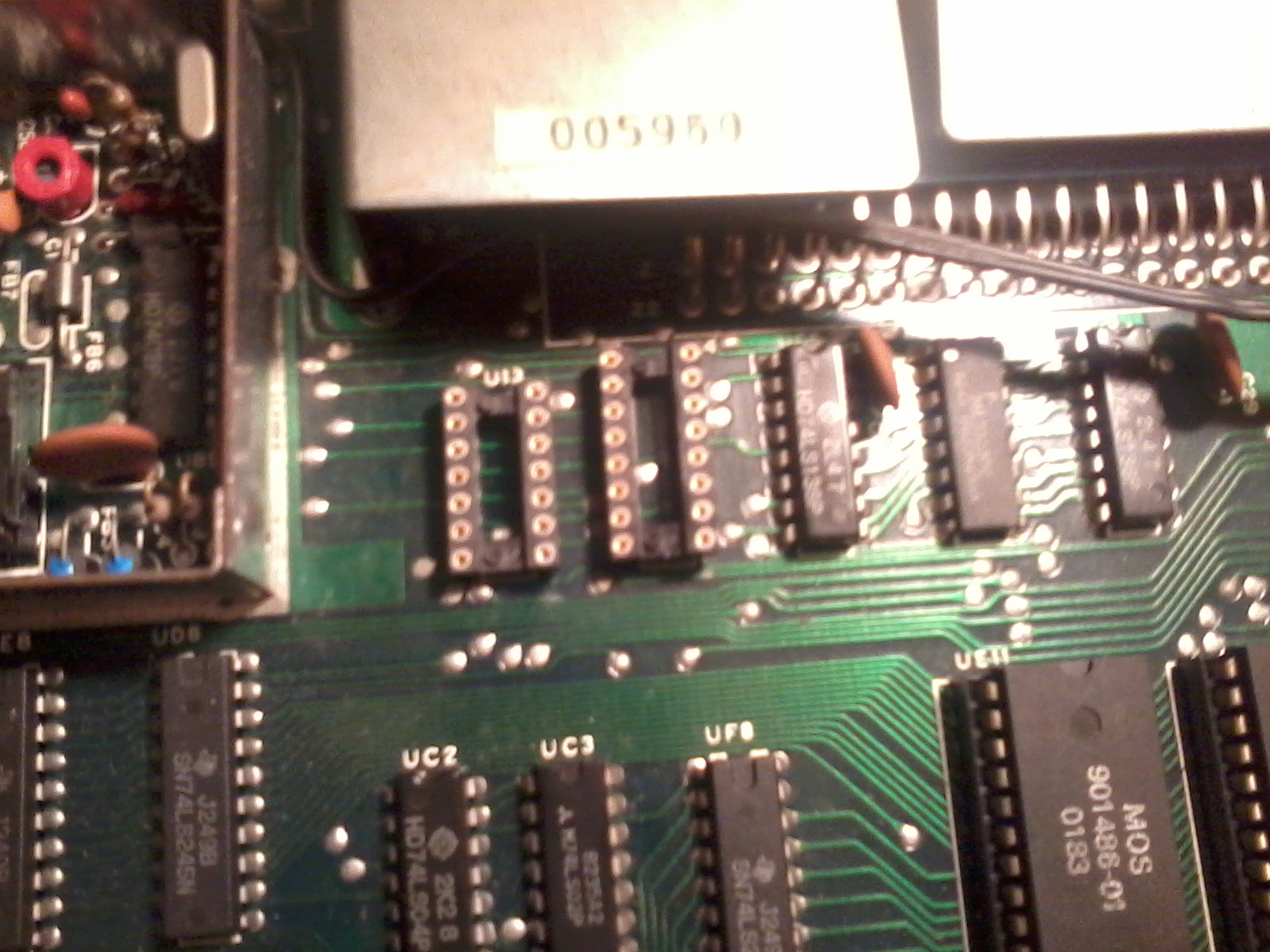
 All the sockets are in .
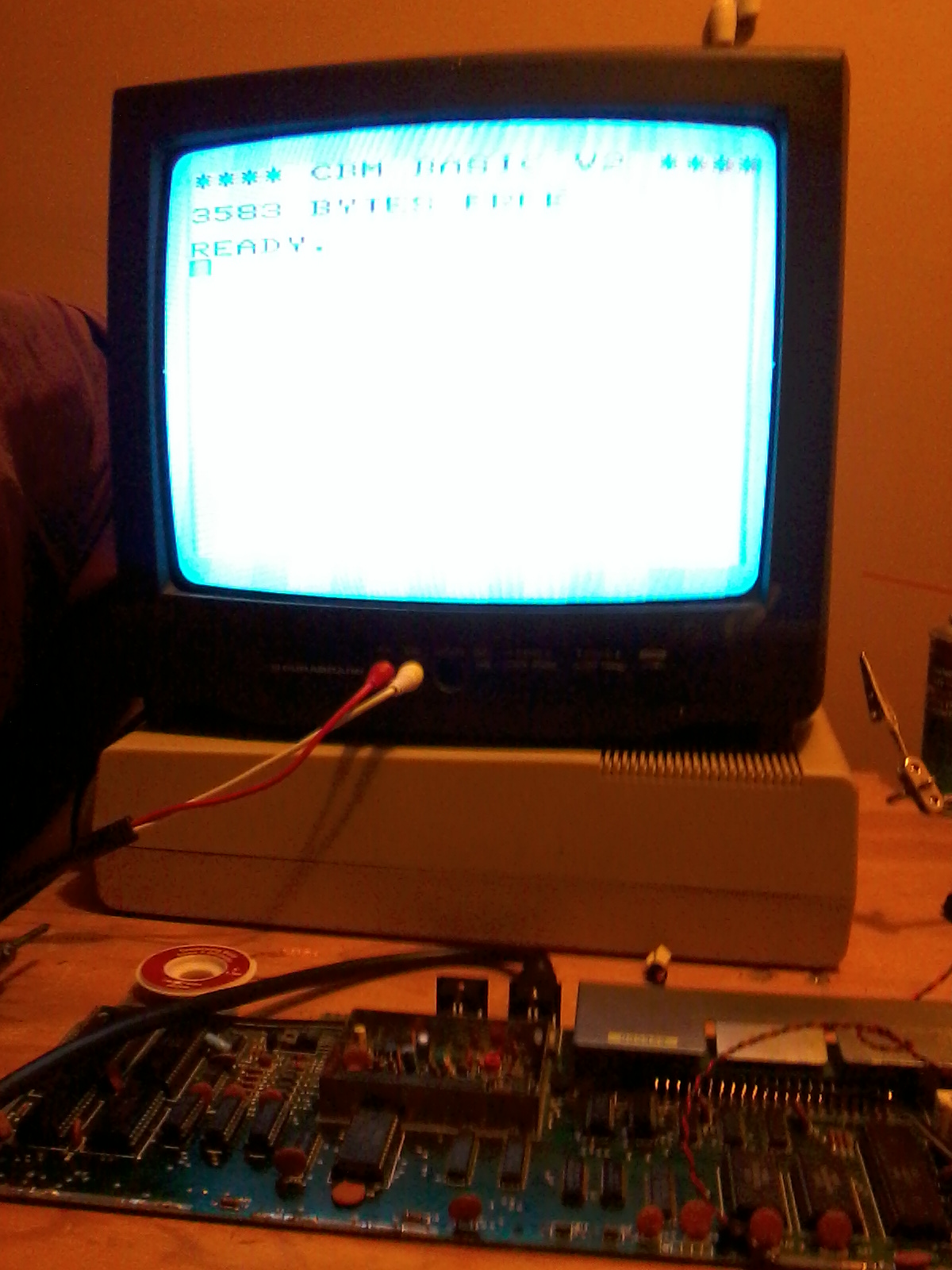 Test one complete.
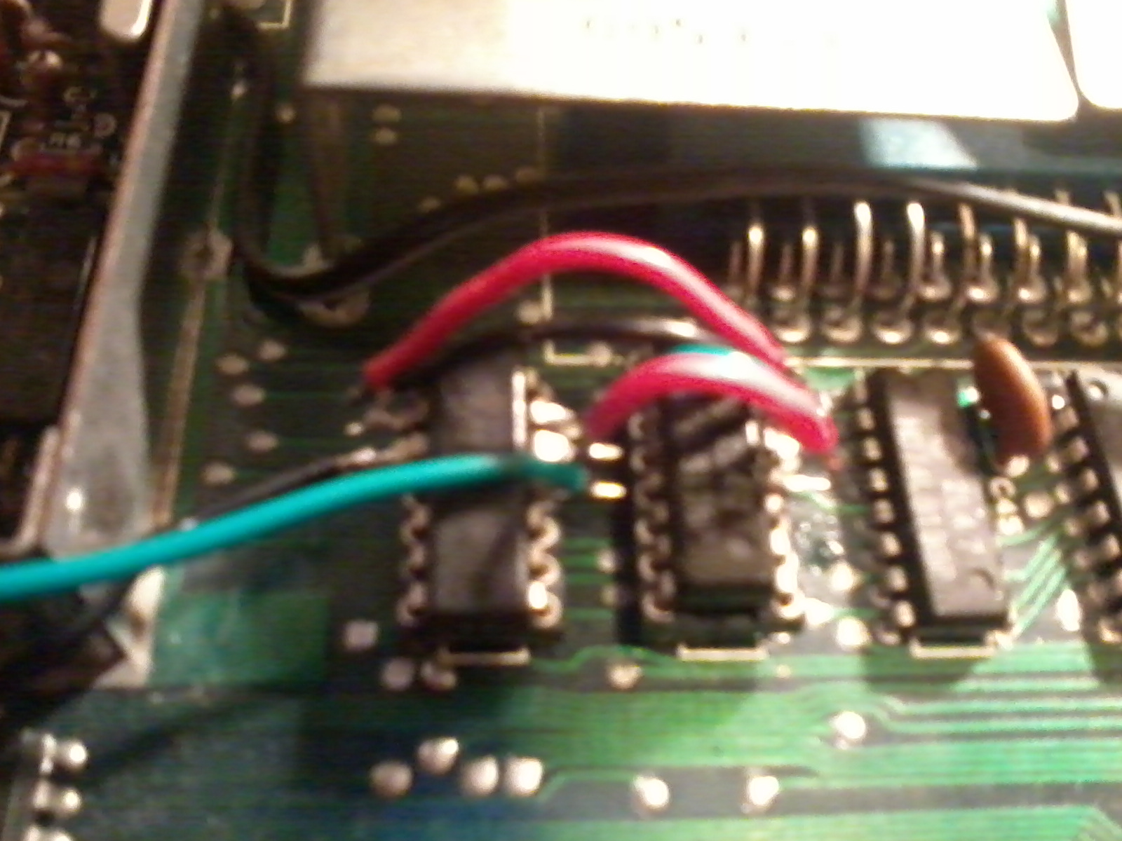
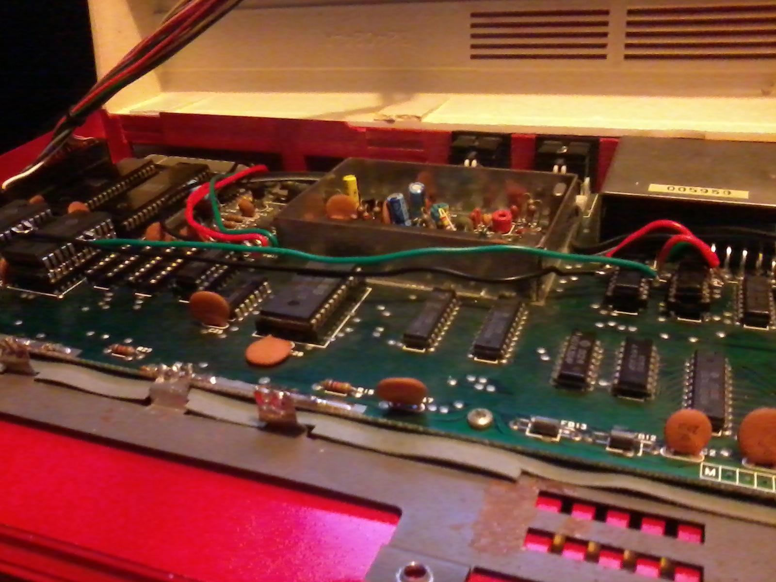
 So the rewiring for the extra screen memory is almost complete.
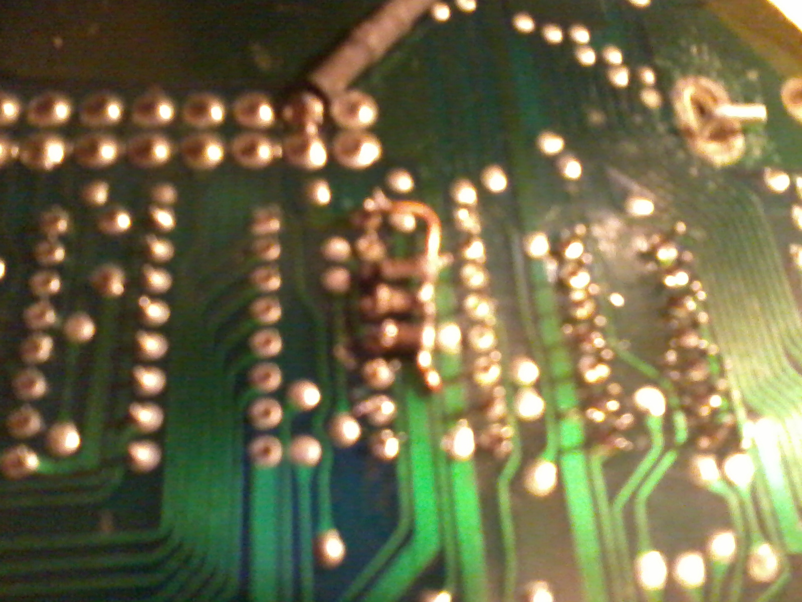 Aside from de-soldering the chips this was the most difficult and frustrating thing to do.
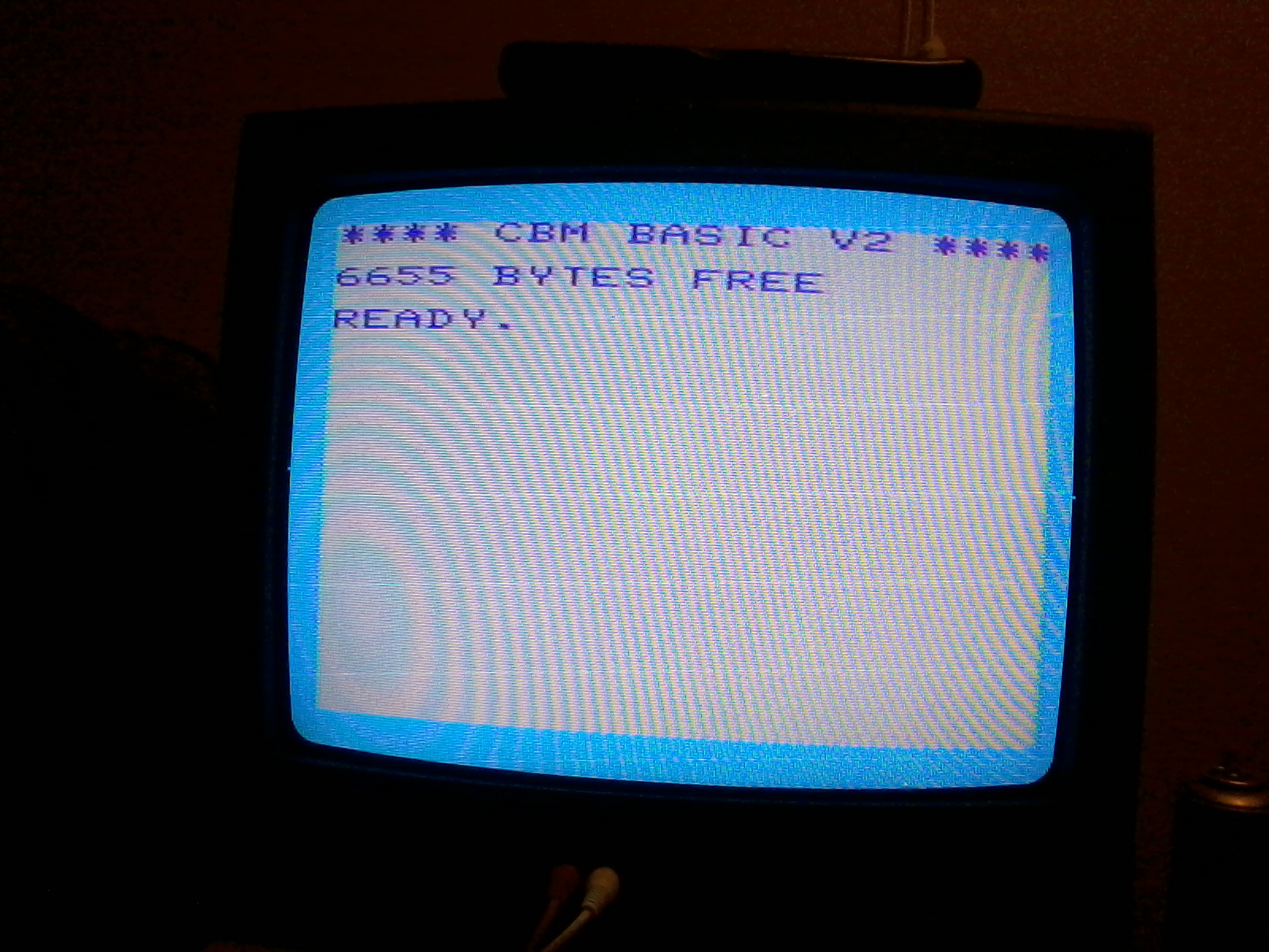 Test two complete.
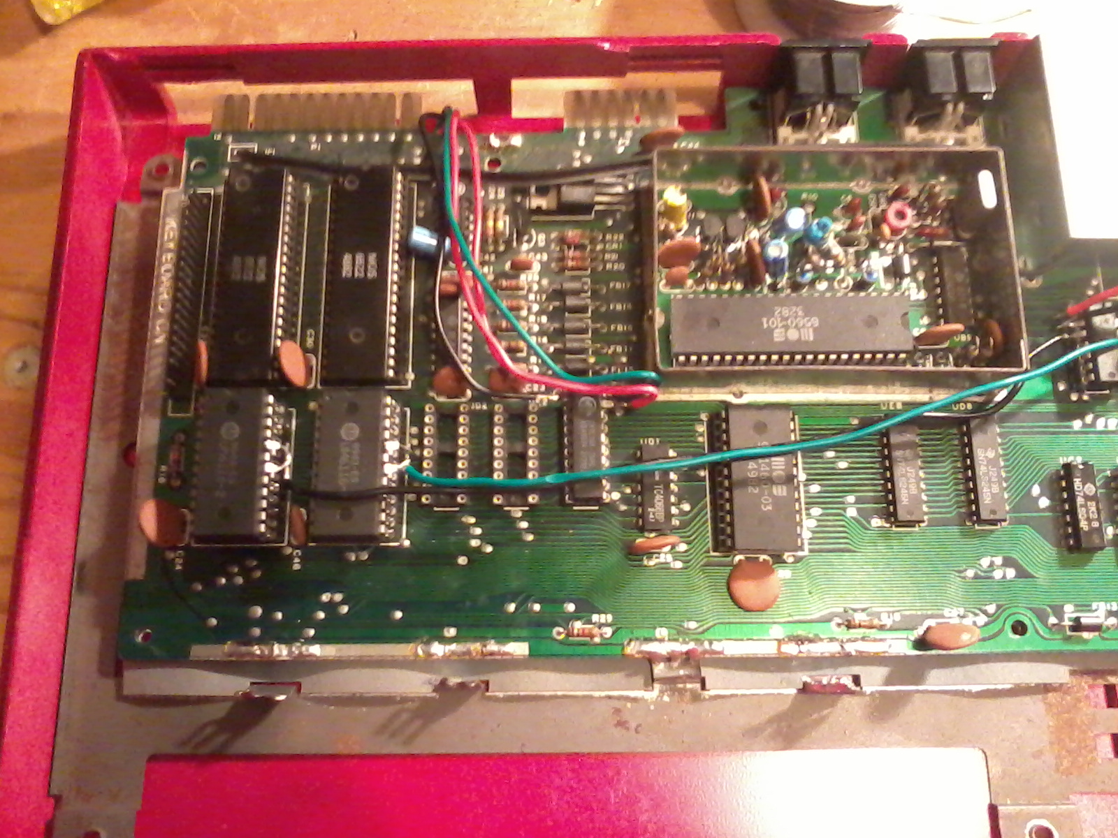
 Although the project only took about 4 or 5 nights, it was over almost 4 weeks. I was very excited to try something.
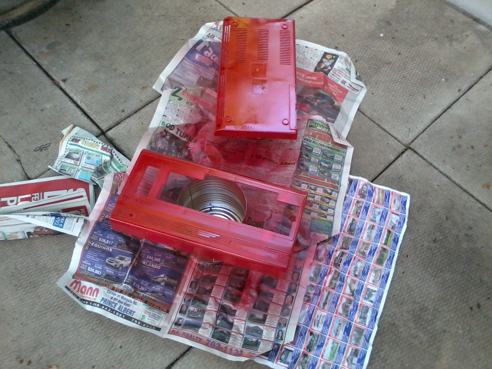 But I thought this special computer should have a special case, so I painted it red.
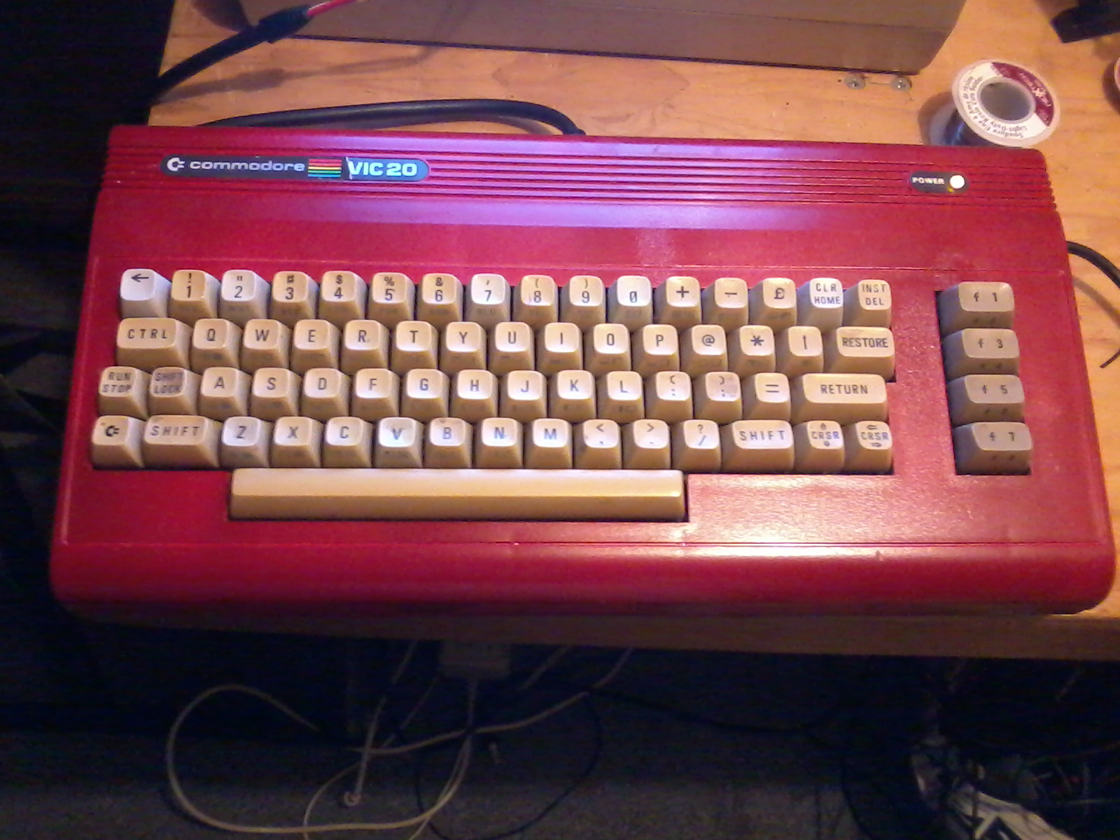 I was going to add a blue LED but it wouldn't have fit the colour scheme, so I added a yellow one.
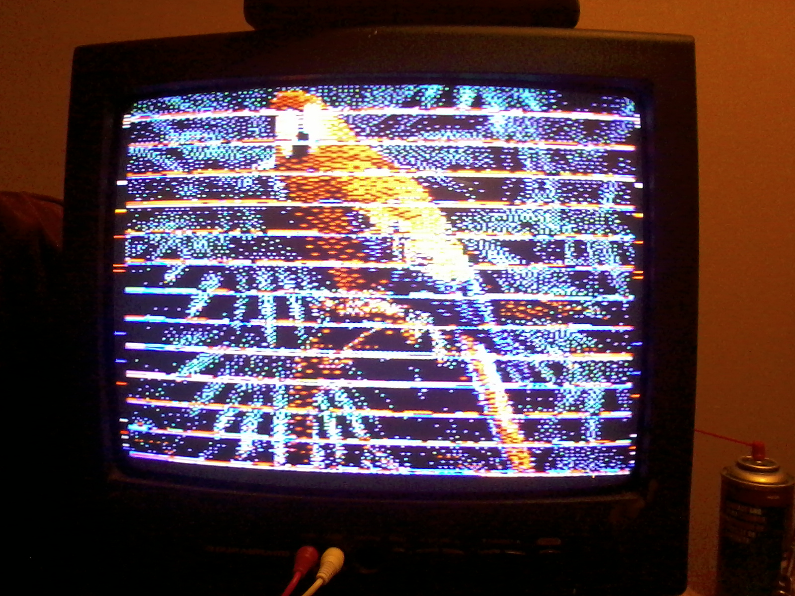 Then the final test. After downloading Mikes NTSC disk and transferring it something was wrong ...
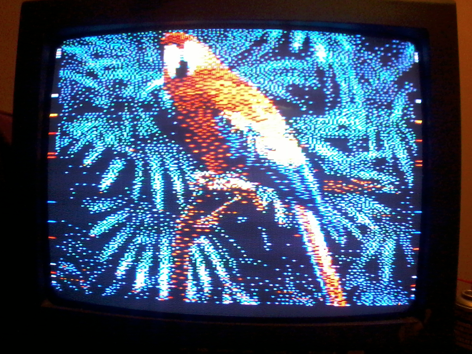 I emailed Mike and he knew what was wrong right away and sent a new program.
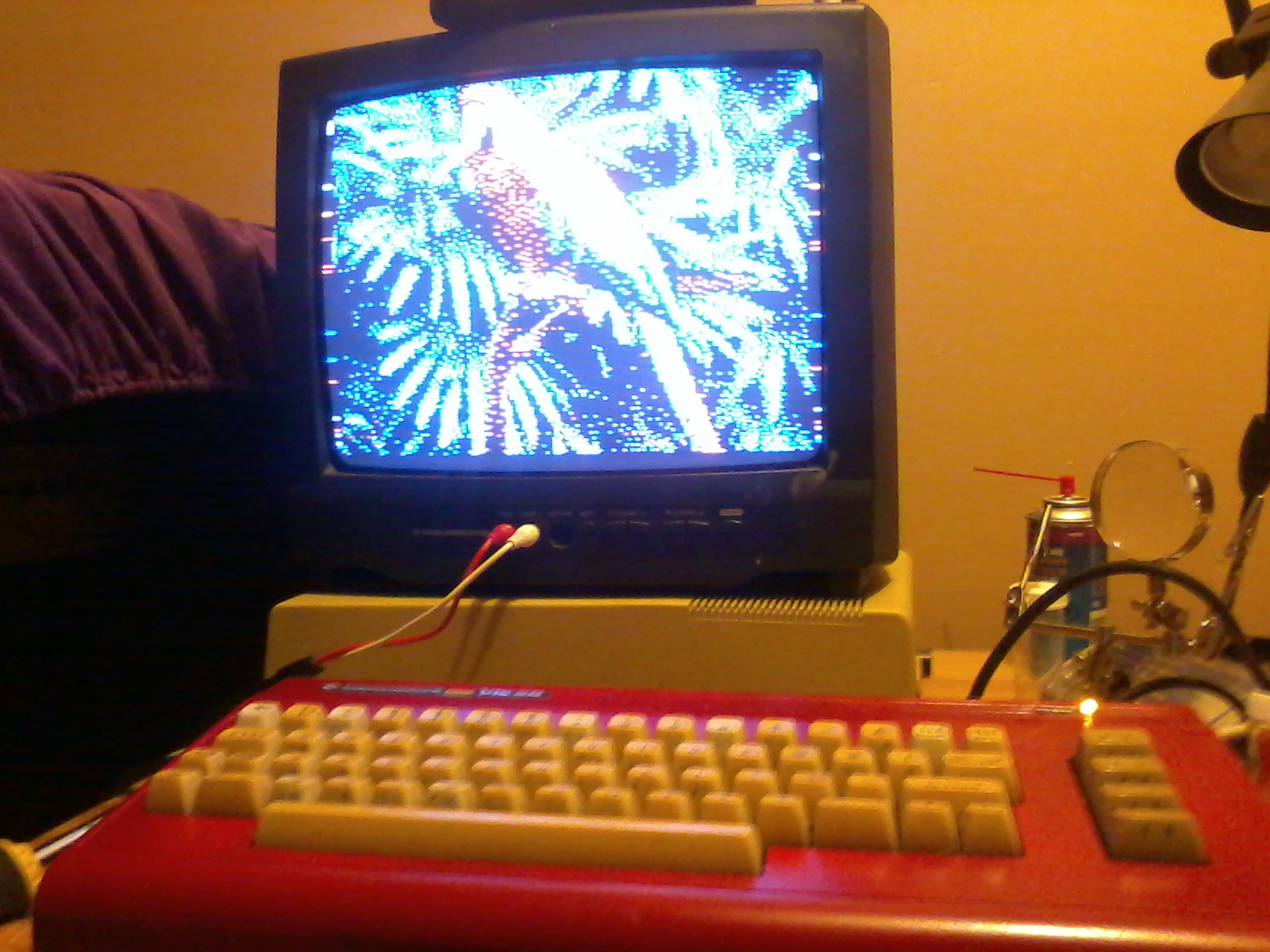 So several nights later I had done it! A successful VFLI mod. NOW I will have to figure out how it works ... so I can do something eVICl with it.